Architecturals |
Civils |
General Arrangements |
Logos |
Mechanicals |
Naval Architecture |
P&IDs |
Tax Maps |
Topo Maps |
Wiring Diagrams
See also our Introduction to Converting PDFs to CAD and examples of our 3D and BIM.
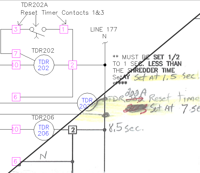
Each illustration shows the CAD on top and the original Scan or PDF below. Normal layer color
conventions have been changed for greater clarity.
Mouse over detail images to magnify. Roll to zoom. Tap on touch screens. We can
supply more example DWGs on request.
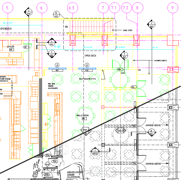
Detail from Plan
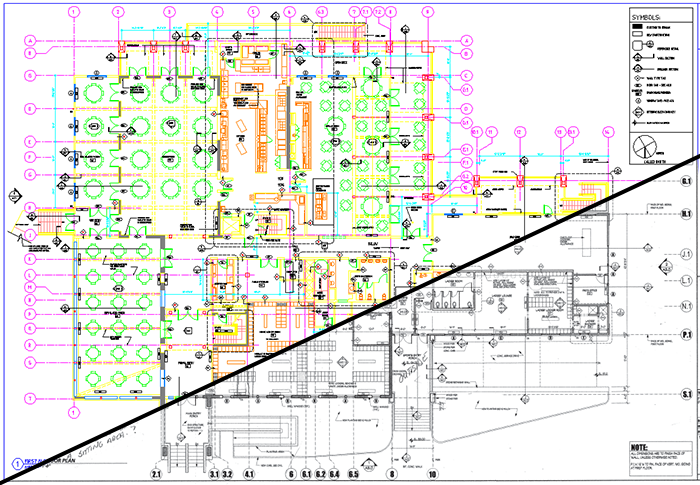
Complete Plan
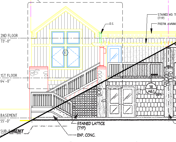
Elevation Detail from Drawing

Complete Elevation Drawing
Architectural CAD Conversion
These plans of a country club were originally drawn by hand. When the club began a remodeling project they scanned in the plans. We converted them to CAD, using a modern architectural layering convention and cross-checked that the indicated dimensions matched those that were scaled off the plans. The architect then used the CAD as the basis for the design of the refurbishment work.
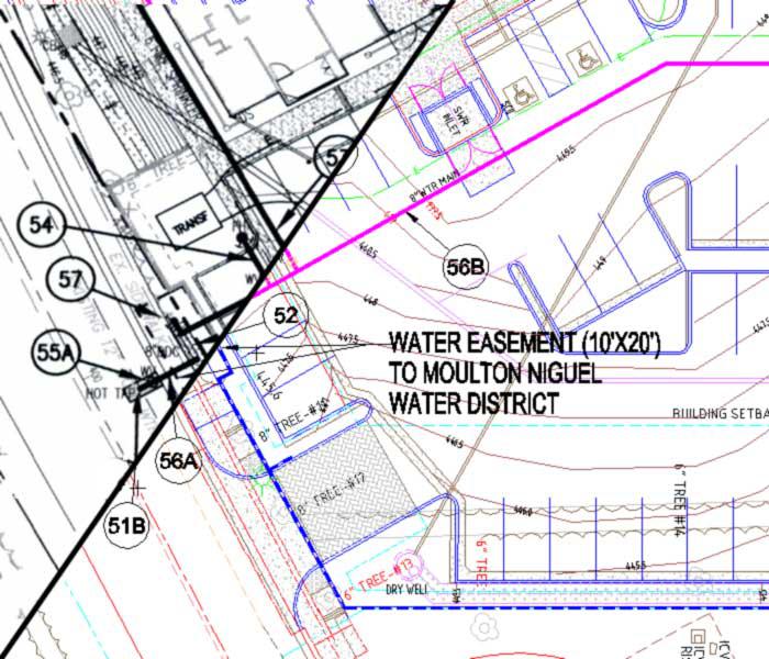
Detail from Plan
Complete Plan
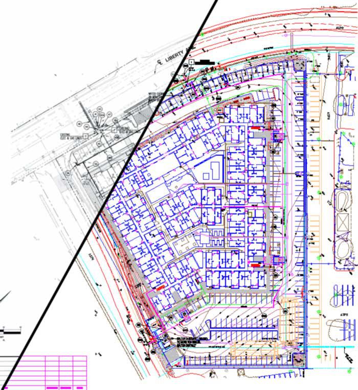
Civil Engineering CAD Conversion
Civil Engineering drawings often contain dense layers of information. This example of a water plan illustrates how our CAD operators do a great job deciphering the content of the scanned original and drafting it in correct, color coded, CAD layers.
Detail from Drawing
Complete Drawing
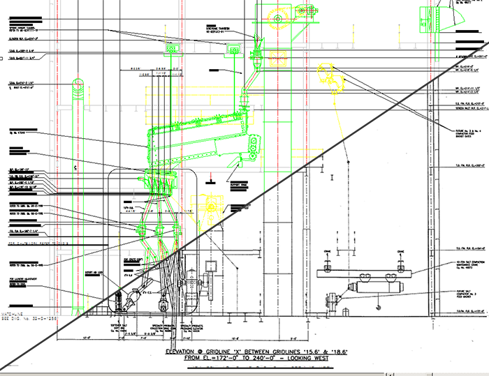
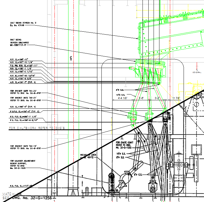
General Arrangement Conversion
This drawing was from a package of fifty converted to CAD in advance of a major upgrade to a chemical plant. The engineering firm that undertook the upgrade used the drawings as the starting point for their redesigns.
Detail from Drawing
Complete Drawing
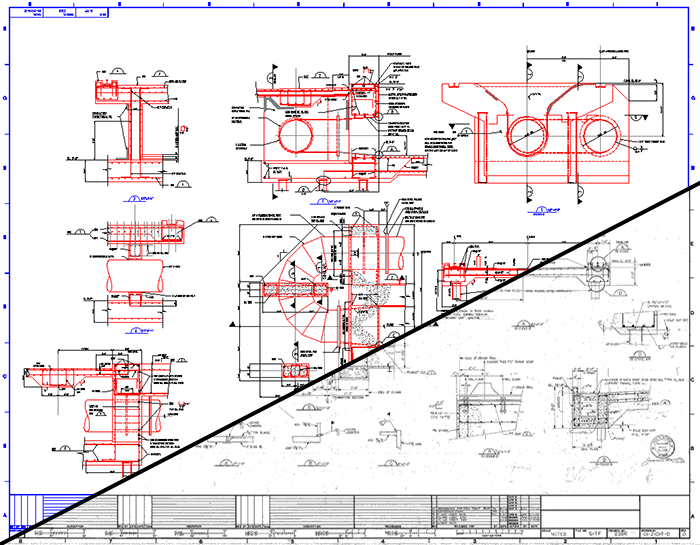
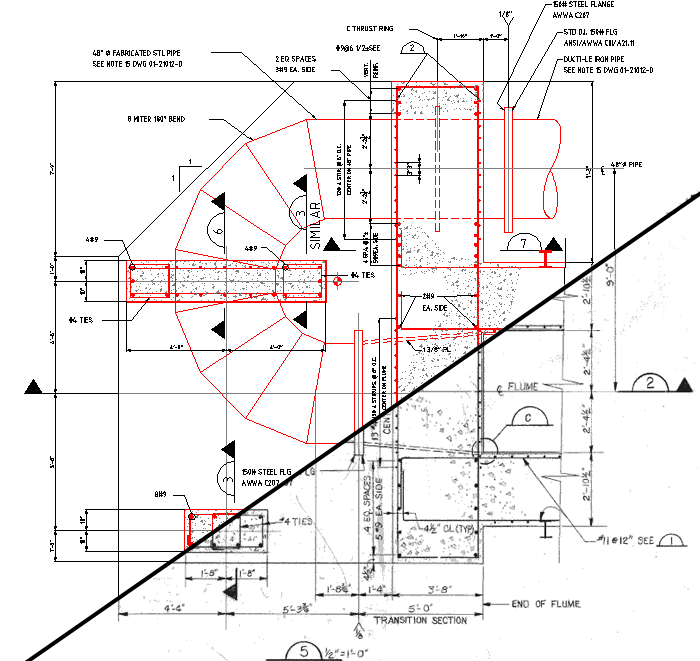
Mechanical Conversion
This drawing was one of a set depicting parts of log flume at a paper company. As is common with older drawings, the paper had distorted over time so the scans were somewhat skewed. Our drafting corrected this and squared up the drawings.
Detail from Drawing
Complete Drawing
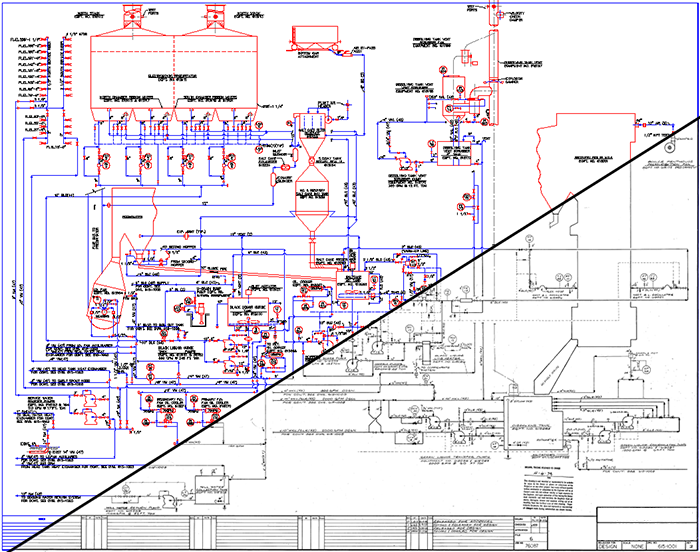
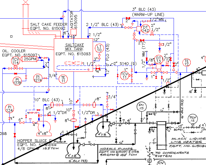
P&ID Conversion
P&IDs are full of small informational details, many of them similar. We pay particular attention to accurate transcription of these.
Detail from Drawing
Complete Drawing
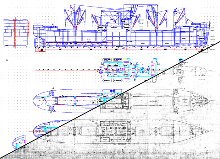
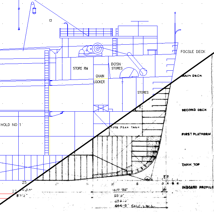
Naval Architecture Conversion
The original Naval Architect's drawings were converted to CAD and used as the basis for a fire control systems project.
Detail from Drawing
Complete Drawing
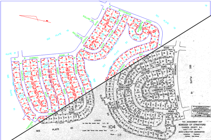
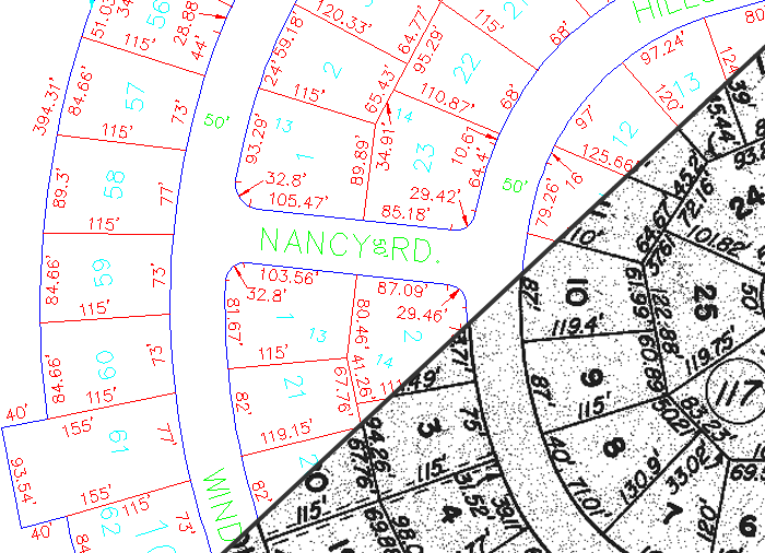
Tax Map Conversion
Though the linework in tax maps is relatively simple the many dimensions and reference numbers must be carefully replicated in the CAD file.
Detail from Drawing
Complete Drawing
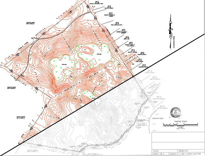
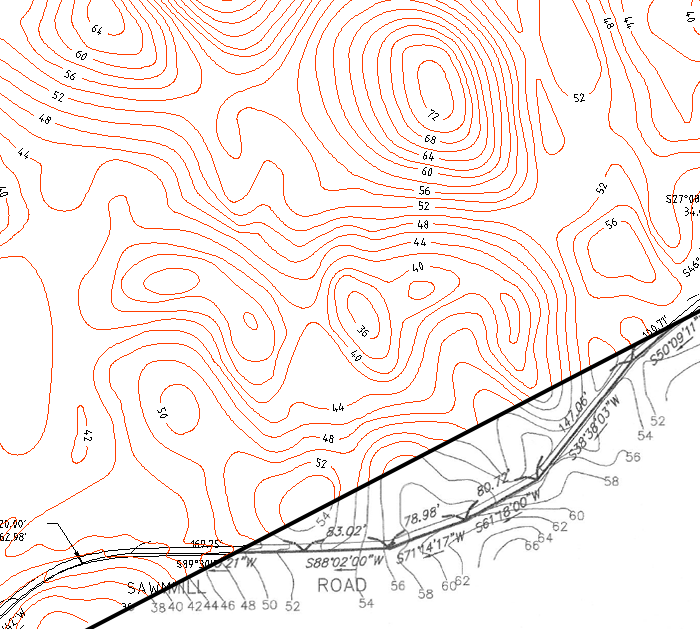
Topo Map Conversion
Conversion of Topo Maps involves careful tracing of contour lines.
Detail from Drawing
Complete Drawing
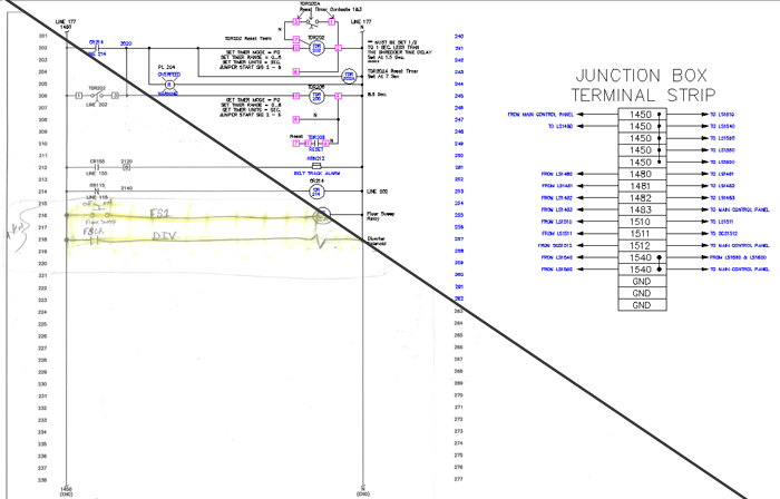
Wiring Diagram Conversion
In this example the conversion required the incorporation of markup (redline) made on the original drawings.
Satellite Image
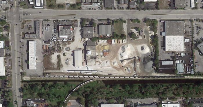
DWG made from Image
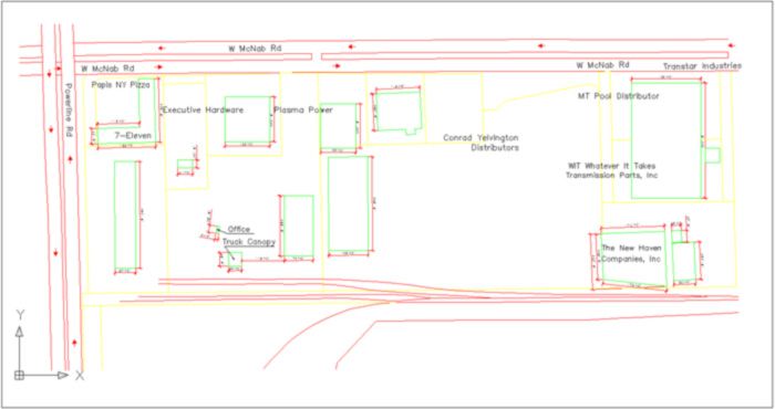
Site Plan from Satellite Image
Provided one accepts the limitations when taking off dimensions from satellite or aerial imagery, it is possible to create CAD site plans.
Logo drafted in CAD
