Why doesn't a scan work in CAD?
When a drawing is scanned it does not become CAD. It is a ‘raster’ image – just a series of dots of different colors
and shades. It cannot be edited in CAD because CAD programs use vectors, not dots, for their lines.
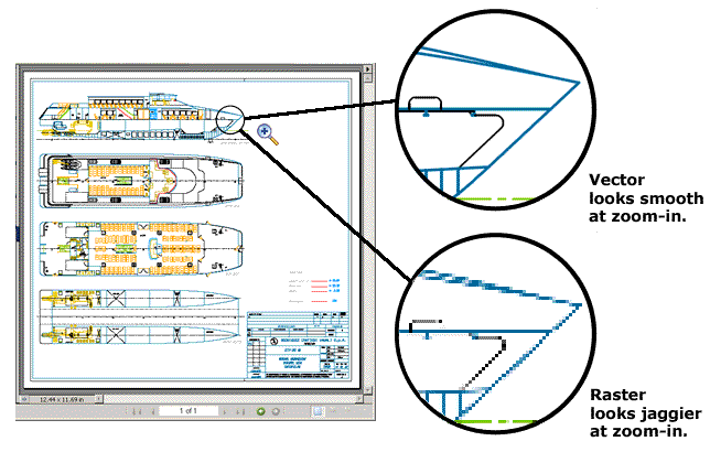
The illustration below shows the difference between vectors and rasters when you look up close. If you open a vector image and zoom in on a detail, the lines appear clearly, no matter how far in you zoom. If you
open a raster image and zoom in on a detail the lines appear jaggy.

The raster image appears jaggy because the lines
have been created using individual 'dots'. When the dots are seen together on a screen our brains
'connect the dots' and we see lines. Raster images are created when a drawing is scanned into a computer. Many PDFs are raster images because they were
created by scanning in the first place. A photo is another example of a raster image.
A raster is usually fine for viewing images, provided the original raster image is of a sufficiently high resolution. By this we mean that there are plenty of dots per inch (dpi). Our brains will do the connecting work.
CAD programs work completely differently. They describe lines mathematically. A CAD program defines a straight line as "start at coordinate x1,y1 and go to coordinate x2,y2". Curved lines and other shapes are defined using more complex mathematical descriptions. You will often see the statement that CAD drawings are "intelligent" because they contain precise dimensions and entity types. This is a misuse of the word since only living creatures have intelligence - but you can see why it is used. A more accurate description of the content of a CAD file is "rich data".
When the time comes to edit a scanned plan or engineering drawing there are four possible approaches:
- You could edit the file in a raster editing software such as Paint or Adobe Photoshop. This is possible if you are skilled in using these applications. The result is still a raster image. Controlling dimensions and overlaying details using raster editing is much harder to do than it is in CAD.
- Use raster to vector conversion software which tries to semi-automatically trace the raster lines into vectors. This works for simple profiles and continuous uninterrupted lines such as logo outlines. It does not work well for dimensioned or complex drawings because the algorithms are not anything like as good as the human brain at interpreting the raster images.
- Hybrid CAD editing, where you insert the raster image that was scanned into a CAD file as a background. This is still a raster and it cannot be edited by the CAD application. But you can then draw over it using CAD vectors. The result is a hybrid CAD drawing which stores both the original raster scan and the CAD lines drawn on top of it.
- Manual redrawing by a proper CAD operator is the best approach. This is what we do. We take your drawing and convert it to a CAD file vector format using proper CAD entities and with all lines and text layered. Everything in it can then be edited using a CAD application, becasue it has been drawn in CAD in the first place. This is the best and most cost-effective approach when your raster drawing has to be used in CAD.